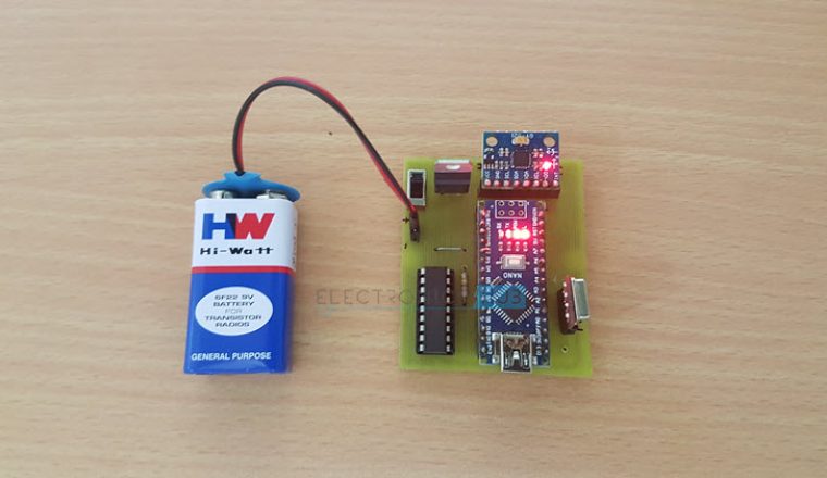
In this project, we have designed a simple Hand Gesture Controlled Robot using Arduino. This Hand Gesture Controlled Robot is based on Arduino Nano, MPU6050, RF Transmitter-Receiver Pair and L293D Motor Driver.Even though the title says it as a Hand Gestured Controlled Robot, technically this robot is controlled by the tilt of the hand.
Preface
A Robot is an electro-mechanical system that is operated by a computer program. Robots can be autonomous or semi-autonomous. An autonomous robot is not controlled by human and acts on its own decision by sensing its environment.
Majority of the industrial robots are autonomous as they are required to operate at high speed and with great accuracy. But some applications require semi-autonomous or human controlled robots.
Some of the most commonly used control systems are voice recognition, tactile or touch controlled and motion controlled.
One of the frequently implemented motion controlled robot is a Hand Gesture Controlled Robot. In this project, a hand gesture controlled robot is developed using MPU6050, which is a 3-axis Accelerometer and 3-axis Gyroscope sensor and the controller part is Arduino UNO.
Instead of using a remote control with buttons or a joystick, the gestures of the hand are used to control the motion of the robot.
The project is based on wireless communication, where the data from the hand gestures is transmitted to the robot over RF link (RF Transmitter – Receiver pair).
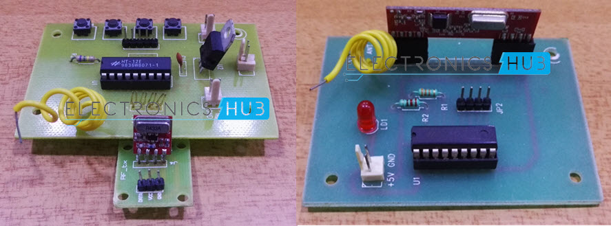
The project is divided into transmitter and receiver section. The circuit diagram and components are explained separately for both transmitter and receiver sections.
Principle of Hand Gesture Controlled Robot
In order to understand the principle of operation of Hand Gesture Controlled Robot, let us divide the project into three parts.
The first part is getting data from the MPU6050 Accelerometer Gyro Sensor by the Arduino. The Arduino continuously acquires data from the MPU6050 and based on the predefined parameters, it sends a data to the RF Transmitter.
The second part of the project is the Wireless Communication between the RF Transmitter and RF Receiver. The RF Transmitter, upon receiving data from Arduino (through the Encoder IC), transmits it through the RF Communication to the RF Receiver.
Finally, the third part of the project is decoding the Data received by the RF Receiver and sending appropriate signals to the Motor Driver IC, which will activate the Wheel Motors of the Robot.
Block Diagram of Hand Gesture Controlled Robot
The following images show the simple block diagram of Hand Gesture Controlled Robot for both Transmitter and Receiver Parts.
Transmitter Block Diagram

Receiver Block Diagram

Circuit Diagram of the Transmitter Section
The following image shows the circuit diagram of the Transmitter part of the Hand Gesture Controlled Robot project.
Components for Transmitter Section
- Arduino Nano
- 434MHz RF Transmitter
- HT-12E Encoder IC
- MPU6050 Accelerometer/Gyroscope Sensor
- 750KΩ Resistor
Circuit Diagram of the Receiver Section
Components for Receiver Section
- L293D Motor Driver IC
- HT-12D Decoder IC
- 434 MHz RF Receiver
- 33KΩ Resistor
- 330Ω Resistor
- LED
- 4 Geared Motors with Wheels
- Robot Chassis
Component Description
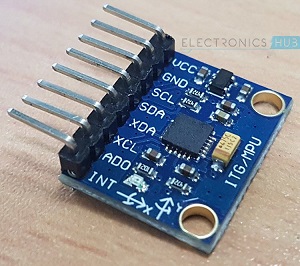
MPU6050
The MPU6050 is one of the most commonly used Sensor Modules by hobbyists and enthusiasts. It consists of Accelerometer and Gyroscope on the same IC and provides 6 Degrees of Freedom (3-axis of Accelerometer and 3-axis of Gyroscope).
RF Transmitter and Receiver Modules
The communication between transmitter and receiver is using RF modules. A 434 MHz transmitter and receiver pair are used in this project.
HT-12E
It is an encoder IC that converts the 4-bit parallel data into serial data in order to transmit over RF link.
HT-12D
It is a decoder IC that converts the serial data received by the RF Receiver into 4-bit parallel data. This parallel data can be used to drive the motors.
Circuit Design of Hand Gesture Controlled Robot
Transmitter Section
The transmitter section of the robot consists of Arduino Nano board, MPU6050 Sensor, HT-12E Encoder IC and an RF Transmitter. The communication between Arduino and MPU6050 Sensor takes place through I2C Interface. Hence, the SCL and SDA pins of the MPU6050 Sensor are connected to A5 and A4 pins of the Arduino Nano.
Additionally, we will be using the interrupt pin of the MPU6050 and hence, it is connected to D2 of Arduino Nano.
HT-12E is an encoder IC that is often associated with RF Transmitter module. It converts the 12-bit parallel data to serial data. The 12-bit data is divided into address and data bits. A0 to A7 (Pin 1 to Pin8) are the address bits and they are used for secure transmission of the data. These pins can be either left open or connected to ground (Vss). In this circuit, Pin 1 to Pin 9 (A0 – A7 and Vss) of HT-12E are connected to ground.
Pins 10 to 13 (AD8, AD9, AD10 and AD11) are the data pins of HT-12E. They receive the 4 word parallel data from external source like a microcontroller (Arduino Nano in this case). They are connected to the pins D12, D11, D10 and D9 of Arduino Nano respectively.
TE’ is the transmission enable pin and it is an active low pin. The data is transmitted as long as the TE’ is low. Hence, Pin 14 (TE’) is also connected to ground.
The encoder IC has an internal oscillator circuit between the pins 16 and 15 (OSC1 and OSC2). A 750KΩ resistor is connected between these pins to enable the oscillator. Dout (Pin 17) is the serial data out pin. It is connected to the data in pin of the RF Transmitter.
Both Arduino Nano and MPU6050 have 3.3V Regulator. Hence, all the VCC pins are connected to a regulated 5V Supply.
Receiver Section
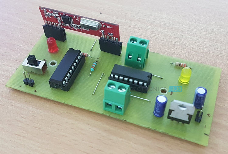
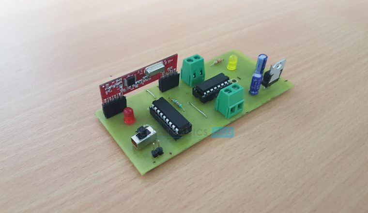
The receiver section of the robot consists of an RF Receiver, HT-12D Decoder IC, L293D Motor Driver IC and a robot chassis with four motors connected to wheels.
HT-12D is the decoder IC that is often associated with RF Receiver. It converts the serial data received by the RF link into parallel data. A0 to A7 (Pin 1 to Pin 8) are the address pins and must be matched with the address pins of the encoder.
Since the address pins of encoder (HT-12E) are grounded, the address pins of decoder must also be grounded. Hence, pins 1 to 9 (A0 – A7 and Vss) are connected to ground. The serial data from the RF Receiver is given to Din (Pin 14) of the decoder IC.
HT-12D has an internal oscillator and an external resistor of 33KΩ is connected between OSC1 and OSC2 (Pins 16 and 15). Pin 17 (VT) indicates a valid transmission of data and this pin will be high when a valid data is present on the data pins. An LED in series with a 330Ω resistor is connected to this pin to indicate a valid data transmission.
Pins 10 to 13 (D8, D9, D10 and D11) of HT-12D are the parallel data out pins. They are connected to the input pins of the L293D motor driver IC (Pins 2, 7, 10 and 15 respectively).
L293D motor driver IC is used to provide the necessary current (for both forward and reverse directions) to the motors. Pins 1 and 9 are the enable pins and are connected to VCC (+5v) along with Pin 16 (which is the logic supply). Pins 3 – 6 and 11 – 14 are the outputs and are connected to the four motors.
Pin 8 is the Motor Supply Pin and is connected to a separate power supply. Hence, you will need two batteries in the Receiver Section; one for the Circuit and one for the motors.
Working of Hand Gesture Controlled Robot
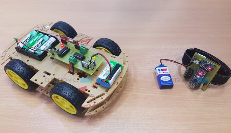
In this project, a mobile robot that is controlled by the gestures made by the hand, is designed. The working of the robot is explained here.
As mentioned earlier, the gesture controlled robot is a wireless operated robot and has two parts: Transmitter and Receiver. When the robot is powered on, the transmitter part, which consists of Arduino, MPU6050, Encoder and RF Transmitter, will continuously monitor the MPU6050 sensor.
This data is captured by the Arduino, which then transmits a corresponding data to the Encoder, based on the orientation of the MPU6050 Sensor. The parallel data received by the encoder is converted into serial data and this serial data is transmitted by the RF Transmitter.
At the receiver section, the RF Receiver receives the serial data and transmits it to the Decoder IC. The Decoder will convert the serial data to parallel data and this parallel data is given to the motor driver IC. Based on the data, the movement of the motors, and hence the movement of the robot is defined.
CODE
/*
ARDUINO BASED GYROSCOPE CONTROLLED ROBOT BY ENGINEER KID
THIS PROJECT WILL HELP YOU TO UNDERSTAND THE ARDUINO MICROCONTROLLER
, MOTOR DRIVER MODULE AND GY-521 GYROSCOPE MODULE IN AN EASY WAY.
WORKING OF THIS PROJECT :-
THE GYROSCOPE SENSOR IS ALSO KNOWN AS THE TILT SENSOR. IT SENSES ITS
MOVEMENTS AND PROVIDES THE VALUES TO THE ARDUINO. THE GYROSCOPE MODULE
WORKS ON ALL THE THREE AXIS NAMELY THE X,Y AND Z. WHEN THE ARDUINO RECEIVES
THESE VALUES IT USES THEM WITH THE IF ELSE STATEMENTS TO DRIVE THE MOTORS ACCORDINGLY.
THE CONNECTIONS BETWWEN THE GYROSCOPE MODULE AND THE ARDUINO ARE GIVEN BELOW.
GYRO<<ARDUINO
VCC<<VCC
GND<<GND
SCL<<A5
SDA<<A4
AD0<<GND
INT<<D2
*****************************************************************************************
***ALL THE BEST***
*****************************************************************************************
IF YOU COME ACROSS ANY PROBLEM REGARDING THE PROJECT FEEL FREE TO
CONTACT ME AT - engineerkid1@gmail.com
You can contact me at :-
Facebook page - https://www.facebook.com/engineerkid1/
Instagram - https://www.instagram.com/engineerkid1/
Twitter - https://mobile.twitter.com/Engineerkid01?s=09
Website - http://electronickida.wordpress.com
*/
#include<Wire.h>
const int MPU_addr=0x68; // I2C address of the MPU-6050
int16_t AcX,AcY,AcZ,Tmp,GyX,GyY,GyZ;
const int trigPin=13;
//Motor A
const int motorPin1 = 5;
const int motorPin2 = 6;
//Motor B
const int motorPin3 = 10;
const int motorPin4 = 9;
void setup()
{
pinMode(trigPin,OUTPUT);
pinMode(motorPin1, OUTPUT);
pinMode(motorPin2, OUTPUT);
pinMode(motorPin3, OUTPUT);
pinMode(motorPin4, OUTPUT);
Wire.begin();
Wire.beginTransmission(MPU_addr);
Wire.write(0x6B);
Wire.write(0);
Wire.endTransmission(true);
Serial.begin(9600);
}
void loop(){
Wire.beginTransmission(MPU_addr);
Wire.write(0x3B);
Wire.endTransmission(false);
Wire.requestFrom(MPU_addr,14,true);
AcX=Wire.read()<<8|Wire.read();
AcY=Wire.read()<<8|Wire.read();
AcZ=Wire.read()<<8|Wire.read();
Tmp=Wire.read()<<8|Wire.read();
GyX=Wire.read()<<8|Wire.read();
GyY=Wire.read()<<8|Wire.read();
GyZ=Wire.read()<<8|Wire.read();
Serial.print("AcX = "); Serial.print(AcX);
Serial.print(" | AcY = "); Serial.print(AcY);
Serial.print(" | AcZ = "); Serial.print(AcZ);
Serial.print(" | Tmp = "); Serial.print(Tmp/340.00+36.53);
Serial.print(" | GyX = "); Serial.print(GyX);
Serial.print(" | GyY = "); Serial.print(GyY);
Serial.print(" | GyZ = "); Serial.println(GyZ);
if(AcX<-6000&&-11000)
{
digitalWrite(trigPin,HIGH);
digitalWrite(motorPin1, LOW);
digitalWrite(motorPin2, HIGH);//FORWARD
digitalWrite(motorPin3, HIGH);
digitalWrite(motorPin4, LOW);
}
else if(AcX>4000&&6000)
{
digitalWrite(motorPin1, HIGH);
digitalWrite(motorPin2, LOW);//REVERSE
digitalWrite(motorPin3, LOW);
digitalWrite(motorPin4, HIGH);
}
else if(AcY<-7000&&-5000)
{
digitalWrite(motorPin1, HIGH);
digitalWrite(motorPin2, LOW);//LEFT
digitalWrite(motorPin3, HIGH);
digitalWrite(motorPin4, LOW);
}
else if(AcY>5000&&12000)
{
digitalWrite(motorPin1, LOW);
digitalWrite(motorPin2, HIGH);//RIGHT
digitalWrite(motorPin3, LOW);
digitalWrite(motorPin4, HIGH);
}
else
{
digitalWrite(trigPin,LOW);
digitalWrite(motorPin1, LOW);
digitalWrite(motorPin2, LOW);//STOP
digitalWrite(motorPin3, LOW);
digitalWrite(motorPin4, LOW);
}
delay(333);
}
you can watch my vedio on youtube about this project:https://www.youtube.com/watch?v=8D9T6GoZ_qU



Comments
Post a Comment